G7400 Composite Video Modification
This modification is meant for G7400 models that lack an RGB/SCART port (i.e.: consoles not manufactured in France). It requires a monitor capable of displaying PAL.
If you have not already done so, you may want to download the G7400 PCB schematics first. This is a 1 Mb download.
Modifying for Composite Video

Required tools and parts:
- Small screwdriver
- Soldering iron (with a small tip)
- Wire cutter
- Resistor 220 Ohm, 0.25W (R3)
- Resistor 330 Ohm, 0.25W (R2)
- Resistor 1k Ohm, 0.25W (R1)
- Transistor BC547B, or any other general purpose, low power NPN transistor
- Stereo audio cable with RCA plugs, or A/V cable.
IMPORTANT: be sure to unplug the console from the power outlet, because the power supply inside the console is NOT isolated.
Turn the console upside down, unplug the controllers, remove the 5 screws and remove the bottom plate.
Remove the RF modulator (metal box) and RF cable.

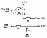
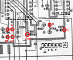
Solder resistors R1 (1k) and R2 (330) at the back of the PCB, according to the red marks in the picture (see Fig. C-2), the base of the transistor to point B, the collector of the transistor to point C, and R3 (220) to the free emitter wire of the transistor (not on the PCB).
When you use an audio cable with RCA plugs on both sides, cut off the plugs at one side of the cable. Solder the outer wires of the cable (shield) to point GND (ground) on the PCB, the inner wire of the video cable to the free end of R3, and the inner wire of the audio cable to point A (R2) on the PCB. Guide the cable through the hole in the console where the RF cable used to be.
Make sure R3 doesn't short circuit to any point on the PCB. Put the bottom plate back in place before testing the console.